For my capstone project (MQP), my team and I are developing an exoskeleton to help those recovering from strokes and injuries. The exoskeleton must take signals from surface electromyography sensors (sEMGs) in order to react to the user's intentions. Naturally, these signals are noisy and must be processed before being sent to the controller. We need to focus on frequencies between ~20Hz and ~450Hz. Additionally, the signal produced by the sEMGs is only about +/- 2.5 mV; this is too low to reliably detect, so we must amplify the signal! The goal was to amplify the signal to an amplitude of 3.3 V, and we were able to reach an amplitude of ~3.2V. This was a great success, especially as the board was made mostly with components I happened to have.

The board consists of two bandpass filters, one for the positive EMG and one for the negative EMG. These bandpass filters are actually made
of a high pass and low pass filter in succession to aid the quality factor of the signal. The frequency response is shown below, as one can see
the phase response leaves a lot to be desired - however since this is not reading data and rather signal amplitudes I decided this weakness was acceptable.
Additionally, the gain is high in all of the regions it should be but it drops too high up in frequency. I will look into ammending component values as
I turn this system into a PCB instead of on a protoboard. The board has yet to be tested in a full system, though this test is coming soon. This coming test
will prove whether or not the board is sufficient for our purposes.
The board uses an LM348N quad operational amplifier for both amplifier stages. The reason for this is that that is the amplifier I had when I began early-stage testing
and it worked very well!


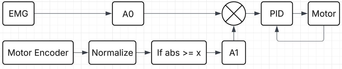
Naturally to properly operate this system, a control system is needed. Outlining our goals we determined that we wanted to provide a firm but not too strong assist to the user. The actuator should never be so strong as to allow the user to lift something they shouldn't. This is to say that when we were designing the system we initially concerned ourselves with the possibility that the motor was providing less than full force as the person was failing to lift something heavy. After much deliberation, however, we determined that if the gain on the motor control system was such that the motor reaches peak torque when the user is at peak effort this should never come into play. Furthermore, given that our intended user is either recovering post injury or a stroke patient, they shouldn't be lifting anything too heavy anyway. With these considerations, we were able to dramatically simplify our system.
Simplicity is incredibly important in engineering and control systems, the more complicated a system is, the more points of failure. Ensuring that this system would never fail and that any failures did not cause harm was of the utmost priority; naturally then, simplicity was certainly a goal. With the above goals and concerns, we designed a control system which measures the effort of the patient, the torque output by the motor, and the position of the arm. The first two inputs to this system are rather obvious, we want to have the motor behave proportionally to the effort the user puts in as this will feel the most "natural". We then use a PID loop to error-correct for the motor's torque output. Where the position of the arm comes in is at the full extension and flexion points of the arm. At this point we are still deciding between using a linear actuator and a brushless motor, the brushless motor does not have hard stops, and thus could theoretically push the arm further than it can go. Obviously, this would be very bad and could seriously injure someone. Therefore, we attenuate the motor's output proportionally to the position of the arm only if the arm is close to the full extension and flexion points. This means that as someone moves their arm fully extended the motor will slow and eventually turn off, preventing injury. Furthermore, we will be integrating limit switches to turn the motor off completely at these points.